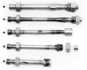
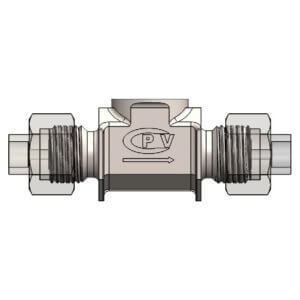
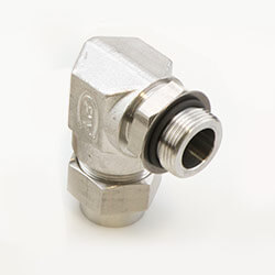
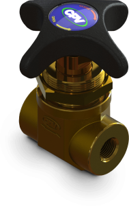
Mark VIII<sup>®</sup> Direct Weld/Braze Fittings Prove Reliable in Tight Spaces

Look to Welding and Brazing Options When Leak Proof Fittings are a Necessity 

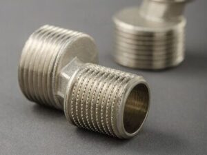
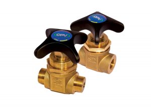
Many valves manufactured by CPV provide leak protection via an O-ring, to supply critical seals within high pressure environments. While greatly reliable, certain applications require an even stronger degree of leak-proof security and in this instance, the best choice might be a welded connection, such as CPV’s Mark VIII® direct weld/braze fittings. This fitting was designed for tight spaces and can be heat sealed for critical applications via welding, orbital welding or brazing. Find out when to specify a welded fitting like the Mark VIII® direct weld/braze, designed for pressures from vacuum up to 6000 PSI.  

Welded Fittings Supply Permanent, Leak-tight Seals  

Welded fittings can be considered superior to O-ring joins for a few reasons. The weld creates a permanent, leak-tight seal that cannot be loosened, while the best O-ring seals can wear out or degrade over time, leading to leaks. In addition, welded fittings can withstand higher pressure and temperature ratings, generally, compared to O-ring joins. Finally, welded fittings are better able to resist vibration and/or mechanical stress, for a robust join that will supply a longer lifespan than an O-ring connection.  

Space constraints are another factor. When they dictate fewer parts or more narrow fittings, or the connection will be located in an area difficult to service, a welded fitting supplies a permanent connection for these small spaces.  

Other applications that might demand a hermetically sealed, leakproof fitting can involve hazardous, flammable, toxic or even costly substances. In these instances, operations require a hermetically sealed fitting to protect worker safety, the environment, surrounding equipment or to try to minimize material losses to maximize the return on investment. As one example, in nuclear power plant instrument lines, tubing connections are most often welded, to withstand both temperature surges and pressure variations, and is one example of an application for Mark VIII® direct weld/braze fittings.  

Potential use case scenarios for Mark VIII® direct weld/braze fittings:  

  • Shipboard or maritime applications 
  • Power plants other than nuclear 
  • Industrial gas filling operations 
  • Critical life support systems in aerospace and undersea apparatus 
  • Marine-based oil and gas drilling systems’ hydraulic controls (in blowout preventer stacks) 

Weld Standards and Benefits of Welded Joints 

Customers are responsible for adhering to industry standards for welding within the application environments governed by the nuclear industry, or Department of Defense for naval shipboard use, for example. Brazing offers the option to make a more permanent connection when joining dissimilar metals, while welding forms a bond between metals of the same type 

A welded fitting offers a greater degree of structural integrity compared to a metal-to-metal fitting or even a joint connection using an O-ring seal, with the weld creating a hermetic seal against leakage, as long as the weld is properly done. Leak testing is always recommended for a welded joint or fitting.  

CPV offers step-by-step instructions for brazing in a tutorial with a photo guide illustrating the process. Find that resource here 

Options for Mark VIII® direct weld/braze Fittings 

Mark VIII® direct weld/braze fittings are available in stainless steel as well as various specialty alloys or metals, such as brass or Monel®. Specifications should include:  

  • Outer dimension 
  • Pressure rating 
  • Wall thickness 
  • Temperature ranges 
  • Connection sizes 

CPV’s main product line for direct weld fittings ranges from an eighth inch to a two-inch outer diameter. The easy connect/disconnect tube fittings connect without swivel joints, for another Mark VIII® advantage.   

Mark VIII® welded fittings replace the leakage prone metal-to-metal sealing of an ordinary hose end connection with positive O-ring sealing. For a permanent branch line, the Mark VIII® direct weld/braze fitting supplies an economical leakproof means of making the connection with the direct weld/braze elbow allowing operators to avoid making a 90-degree bend in a tube, which can crimp the tube decreasing material flow capabilities or stress the metal.   

The Mark VIII® direct weld/braze socket is available in various configurations including direct couplings, elbows (including 90 and 180-degree bends), a Tee connection and o-ring face seal unions. The fittings supply a cost-effective solution for tight fitting joins or a permanent branch line. In addition, the fittings adapt easily to a vast library of valve types, sizes and configurations, available from CPV, for a single source supplier.  

CPV keeps Mark VIII® direct weld/braze fittings and its selection of valves in stock, for a quick turnaround. It offers size changes in the form of reducers or increases to meet custom connection sizes when required.  

Trust CPV’s vast experience when requiring a fitting designed for weld and braze applications, to supply a permanent, hermetically sealed connection in critical applications for maritime use, power plants, industrial gas operations and manufacturing. For more information, visit our main company site at www.cpvmfg.com.    


“O” Isn’t Always for Obvious—Critical Considerations for Selecting O-Rings that Won’t Fail

A simple component that can cost pennies for a single unit has a ubiquitous presence in industry for more than 100 years, supplying critical seals for valves and pipe fittings in devices and hydraulic systems that enable the existence of modern transportation, manufacturing and more. Invented at the beginning of the 20th century, the O-ring gets its name from its shape, an open circle shaped like the letter “o.”

Its purpose is to provide a mechanical seal that contains liquids or gases when placed in a joint or space between two components, usually made of metal. An O-ring operates under higher pressure environments than other gasket styles. Proper O-ring selection can make a significant difference to workers’ health and safety and the success or failure of industrial systems and machinery.  

The Self-Energizing Seal Formed by an O-Ring

O-rings form a seal when squeezed between two adjacent surfaces that are pushed together, usually two metal surfaces. The O-ring sits in a space or joint between these two parts, and as it is compressed it forms a tight seal. The contact stress between the O-ring and the surface needs to be greater than the fluid pressure to prevent the fluid or gas from escaping.

As pressure increases, so does compression on the O-ring, which up to a point, increases contact pressure and improves the O-ring’s sealing power. This positive feedback loop, or the correlation between increased pressure and an increased seal is called “self-energizing.”   

O-rings are easy and generally inexpensive to manufacture, small, easy to install and require little to no maintenance. However, for such a simple component, there are several factors that impact O-ring performance and therefore selection, including the application temperature, sealing pressure or psi, chemical compatibility between the gases or liquid being contains and the O-ring polymer or material, and more.  

Purchasers can determine an O-ring’s size based on the first three digits of a seven-digit number assigned to each O-ring, given in ANSI/SAE AS568A. The last four digits differ depending on the O-ring manufacturer, but generally indicate the type of material used to make the O-ring.  

Material Selection For an O-Ring

Selection and O-ring sizing are paramount considerations for proper O-ring performance.  

The selected material compatibility with the flow media, or the gas or liquid passing through the system is critically important to avoid material degradation and O-ring failure. CPV relies on a Parker O-Ring Handbook, which lists thousands of gases and liquids alongside material compatibility to aid with O-ring material selection. The gases and temperatures are cross-referenced with polymers.  

1. Temperature range

Each type of material has a low and high limit. The O-ring material selected must match the projected temperature range it could encounter in the system or the surrounding environment to avoid failure.   

2. Chemical capability

Alongside temperature range, this could be the most important characteristic when determining O-ring material selection, to avoid incompatibilities that could damage the O-ring and break its seal.  

3. Durometer

This defines the hardness or compressibility of the O-ring material. Most O-rings operate within standard range, with nitrile or a rubber O-ring rated at 75, while a Fluorocarbon Viton, a standard at CPV, is rated at 90. The higher the durometer number, the harder the material.  

A softer material could be subject to extrusion. CPV generally installs O-rings in the face seal. The Parker handbook also helps specify O-ring types according to connection point, whether within a piston, a ceiling area, a face seal, and so on. The durometer and compressibility desired depend on the application.  

4. Gland depth

This defines the clearance or depth of material for an O-ring such that, when subjected to pressure, the O-ring material does not extrude into the gap between pressure points. Extruded O-ring material can fray or degrade, limiting the O-ring’s service life and negating the seal it provides.  

5. Cost

O-rings fabricated of standard materials are inexpensive. Specialized materials or larger sizes rise in price, sometimes sharply. Purchasers already aware of supply chain issues, should know that some specialty materials for O-rings are quite limited and plan accordingly.

As one example of a specialty material, FFKM or perfluoroelastomeric compounds, offer improved resistance to chemicals and high temperatures compared to fluoroelastomers, but can cost significantly more. Specialty sizes that require a new mold also increase the price and the timeframe for project completion and delivery.  

6. Shelf life

Many materials offer almost unlimited shelf life, for example, O-rings made of fluorocarbon. Others have a 10–15-year shelf life. Once an O-ring is in service, its lifespan depends on the environment.

There could be debris introduced into the system during cleaning or a purge that cuts the O-ring. Caustic materials also can shorten the O-ring’s lifespan. For example, ammonia-based cleaners used within a system will, over time, corrode metals and damage the O-rings.   

Proper maintenance and inspections can help extend O-ring serviceability and determine whether it needs replacement, typically an easy process. After some simple lubrication, the O-ring can slip into the groove and seal. A dry seal will never seal as well as one that is lubricated.  

Common Causes of O-ring Failure

O-ring manufacturers provide useful information on proper care and selection. There are numerous potential causes of O-ring failure in mechanical systems. These can include:  

  • Compression set—an elastomeric material flattens, or fails to return to its original size after compression 
  • Extrusion and nibbling—An O-ring that has edges which protrude outside of the sealed area 
  • Spiral failure—A seal that is excessively compressed and cuts the O-ring 
  • Explosive decompression—When high-pressure gas becomes trapped within the internal structure of the seal, the gas expands to match external pressure, causes blisters and ruptures on the O-ring 
  • Chemical degradation—Incompatibility between the O-ring’s elastomer and chemical exposure 
  • Thermal degradation—surpassing the high-temperature limit of the elastomeric material and/or compound 
  • Abrasion 
  • Improper installation 

O-SEAL® and Mark VIII® Union Fittings’ Superior Seal

CPV offers two proprietary union fitting lines: the O-SEAL® and Mark VIII® fittings. These are mirror opposites and therefore not cross compatible for use, with the differences in the thread piece and the tailpiece and positioning of the O-ring groove.  

The O-SEAL  product line is designed for pipe connections with limited TUBE options, while the Mark VIII product line is designed for tube connections with limited PIPE options.  

The Mark VIII line of stainless-steel shutoff and regulating valves offer a soft-seated valve design for trouble-free operations in many industries, such as chemical processing, with the highest tolerances and reliable, leak-proof service. The O-SEAL line offers an ergonomic handle design for greater operator comfort and ease of turning.  

Each supplies numerous benefits to the end user.  

  • Two flat mating surfaces with an O-ring nested between and a respective Union Nut creates a positive bubble-tight seal 
  • O-rings are fully enclosed and compressed within the completed union, to avoid leaks and to protect the O-ring from potential exposure to caustic substances or damage.  
  • System integrity is protected with the unique design of CPV O-SEAL and Mark VIII fittings, which do not deform or distort the tubing/piping in a system, as compression or flare fittings can 
  • Many connection options are available in pipe and tube size 

Trust CPV’s vast experience supplying valves and fittings for decades for mission critical operations in military vessels, industrial gas operations and manufacturing, to help match the proper O-ring for your application. For more information, visit our main company site at www.cpvmfg.com.   

Oxygen Valve Quality Hinges on Compatibility and Cleanliness

Any compressed gas poses a potential risk of ignition and corresponding hazards. Oxygen for example, does not burn by itself. However, it supports combustion and, if not properly contained and managed, oxygen can react explosively or cause spontaneous ignition of other materials. This risk increases as oxygen is put under pressure and as temperatures rise.  

CPV Manufacturing fabricates oxygen control valves for oxygen filling systems. Several industries and applications rely on pressurized oxygen stored in cylinders or containers, such as medical, pharmaceutical, chemical, welding, and waste treatment, among others. Quality, durability, and sensitivity all factor into selection of an oxygen valve that supplies the proper balance of control and protection.  


Oxygen Highly Regulated Due to Hazard Potential

OSHA standards regulate bulk oxygen systems installed on industrial and institutional consumer locations. The U.S. Department of Transportation (DOT) considers medical oxygen a hazardous material, regulating its transportation, and the U.S. Food and Drug Administration (FDA) classifies it as a prescription drug.

State fire codes regulate its handling. International agencies are no exception, with a publication available from the European Industrial Gases Association (EIGA) that discusses the valves involved in their control and specifications for a proper oxygen valve.  

Oxygen Valve Purpose and Placement 

An oxygen valve controls and regulates the flow of pressurized oxygen gas, stored in cylinders or traveling through pipelines. Of all the components within the system, the part most prone to issues and subsequent system failure is the valve.

Issues related to an improperly functioning oxygen valve can include rapid pressure change and subsequent heat generation or leaks. Many of these issues and their associated dangers are discussed in a previous blog post found here 

Quality and Durability Begin with Compatible Material Selection

CPV manufactures all oxygen valves of either naval brass or Monel®, depending on customer preference. Naval brass is a copper alloy that contains zinc for extra strength in fact, making naval brass stronger than other types.

The zinc content in naval brass (39%) also makes it less ductile than brass containing less zinc. A hint of lead helps make it machinable and the addition of one percent tin increases its corrosion resistance.  

Monel(®) is a nickel/copper alloy and typically more expensive than naval brass. Either choice is highly compatible with oxygen applications.  

Customers should avoid oxygen valves made of materials susceptible to oxidation or corrosion, which will weaken the valve and could create a leak. An iron containing material for example, can add moisture to the oxygen, stimulating a chemical reaction that will lead to corrosion.  

Copper alloys have proven to be the most effective among metal options to resist ignition because a copper alloy has the slowest combustion rate. For any type of hazardous gas containment or control, naval brass is a preferred selection for fire and explosion safety purposes.  

Oxygen Cleaning and Government Certifications

Our cleaning process, CPV OX-1, meets the cleaning standards for oxygen cleaning and packaging per the Compressed Gas Association (G-4.1) and ASTM-G93, or related cleanliness standards.  

Separate standards exist for government issue valves. CPV Mfg. and its aqueous component cleaning process recently received approval by NAVSEA for MIL-STD-1330D and MIL-STD-1622B Oxygen Cleaning.

Obtaining this approval enables CPV to meet the needs of the U.S. Navy and other applications that would benefit from military grade or intensive cleaning standards.  

The MIL-STD-1330D applies to other systems outside of oxygen, including Department of Defense Standard Practice, Precision Cleaning and Testing of Shipboard Oxygen, Helium, Helium-Oxygen, Nitrogen, and Hydrogen Systems.  

Reliability and Design Functionality

CPV earns the business of new customers who come to the company because their other valves are leaking and are unreliable. CPV valve customers will find our oxygen valve is the most robust and well-designed oxygen valve available. While no valve is ever completely worry free, operators can anticipate a service life that lasts for thousands of cycles without leaking or other issues.  

In many cases, CPV valves are rated for higher pressures than most competitors. In the United States, an oxygen valve pressure expectations are typically a maximum of 4,500 PSI (307 BAR). CPV oxygen valves exceed that to meet overseas standards for 6,000 PSI (414 BAR) 

Our valves also feature a soft seated design, which includes a Vespel® SP-21 Disc for bubble-tight, leak-free performance, at the highest-pressure ratings for oxygen valves.  

Clean Room Packaging and Training

CPV expanded its cleanroom in 2021 and is certified to meet ISO 14644 Class 7 standards. Our employees are trained and certified as Oxygen Clean Workers and validated to meet MIL-STD 1330D standards.  

All oxygen valves manufactured at CPV are thoroughly wiped down and packaged in the clean room in a double-layered vacuum-sealed bag, protecting them from moisture or contamination up to the point of installation.  

Find more information, including specifications and available sizes for the CPV OXNB ® O-EAL® Series of valves includes a Naval Brass Oxygen Valve, for oxygen service in fill plants, high-pressure manifolds, and other piping systems, visit pages 32 and 33 of our catalog.

The CPV GSB Master valves also service high-pressure gas shutoff and control, with approval for 6,000 PSIG operating pressure in oxygen service for commercial applications worldwide, for safe, reliable control.  Learn more about GSB Master Valves or visit our main company site at www.cpvmfg.com 


Master Valves: The Importance of Ergonomics in the Manufacturing Industry

Manually operated valves, otherwise called master or control valves, are a critical component for refineries, industrial gas production facilities and distribution centers. These valves control the movement of gas to fill industrial gas cylinders, or that traverse pipes for processing.

Due to their ubiquitous presence, these master valves must offer operators reliability, durability, cost effectiveness and one other characteristic not always factored into the design— ease of use          

The original equipment manufacturers (OEMs) that fabricate or construct the manifolds, fill plants, panels and high-pressure piping systems need a reliable partner for these integral components.

CPV Manufacturing is a world-renowned industrial valve manufacturer with a reputation built on our precision craftsmanship of robust, high-pressure solutions engineered to withstand the most demanding conditions.  


Safety First

The Compressed Gas Association and regulatory agencies like OSHA offer information about the hazards of compressed gas cylinders of all types, dangerous due to the high pressurization of their contents. Gaseous oxygen packaged in compressed gas cylinders serves multiple purposes and industries around the globe. These include the recreational, medical, power, chemical processing and metal refining industries, among others.  

This particular compressed gas also requires unique safety measures or extra requirements in regard to medical or industrial oxygen cylinder filling. This includes having the valve complete and pass an oxygen surge pressure test, which evaluates the ignition sensitivity of the valve.  

In addition to the hazards associated with a highly compressed gas, oxygen cylinders present the risk of fire. Any valve designed for use in this type of application must obtain an oxygen-safe approval at a specific operating pressure, without showing any indication of ignition failure.  

Dependability

Operators expect this type of valve to operate flawlessly for thousands of cycles, and ideally, do so without maintenance. CPV master valves offer worry-free operations for countless hours of smooth, accurate, efficient, and consistent filling of valves and cylinders.  

Ergonomics or Ease of Use

During many years of operation, multiple industries have relied on brass hand valves, although not without some difficulties for the operator. Operator fatigue or other ergonomic repercussions stem from a few common characteristics associated with these valves. Namely, most require high torque to open and close, repeated numerous times over the course of a single shift.  

Plant operators and operations can benefit from a valve with an ergonomically designed handle. The GSB master valve from CPV requires low torque to open and close while still providing a bubble-tight seal.   

Consistent Sealing

While constructing a more ergonomically friendly master valve, it is critical to ensure leak rates are controlled. In addition to ergonomics, leak rates both internally and externally have historically created issues with master valves.  

Any components such as seals which can degrade over time, can cause parts failure. Leaky or degraded seals can force a company to replace these master valves as often as every three to six months. Despite their generally economical price point, frequent replacement of even an inexpensive part can unnecessarily strain a capital expense budget, not to mention the added maintenance impact and associated downtime for replacement.  

The Answer

The CPV GSB Valve answers all critical performance factors for a master valve that is reliable, dependable, durable, safe and ergonomically designed for ease of use.  

Highest Pressure Rating in the Industry

The CPV GSB Valve is rated for 6,000 PSIG (414 bar) for Oxygen Service for commercial applications worldwide. It has passed oxygen pressure surge testing with 100% oxygen gas, approved by WHA International, Inc. for ISO 10297 and ISO 7291. In this case, the master GSB valve was tested up to 7,200 PSIG (496 bar) in oxygen, with no sign of failure or leaks.  

CPV Manufacturing’s GSB master valve is the only master or control valve available that meets these stringent requirements. OEMs can rely on the GSB master valve for safety and reliability for high-pressure cylinder filling and processing projects.  

Leak Prevention

CPV prevents leaks by offering the GSB valve fitted with our O-Ring Face-Seal, or O-SEAL separable union connections. This valve is rated for 7,800 PSIG (538 bar) service in inert gas applications, including acetylene, helium, hydrogen, nitrogen, mixed gases and others.  

Ergonomic Design 

The larger, four-prong aluminum handle has an updated design to make it even easier to operate. Its performance was tested internally and externally with several customers.  

In just four turns, the master valve can open or close and with a lower torque than the competition. Further, there are no leaks for a bubble-tight seal for the life cycle of the valve. While other valves become more difficult to turn after multiple cycles, the master valve from CPV Manufacturing remains easy to turn supplying trouble-free operation for thousands of cycles.  

This is a considerable benefit considering the number of valves present on a single panel. There can be anywhere from a few to more than a dozen valves on an individual control panel.  

Thorough Testing

Many manufacturers order sufficient quantities to maintain continuous production without waiting for replacement parts. Each GSB Valve from CPV Manufacturing is fully tested and vacuum sealed to preserve optimal product integrity and cleanliness 

This GSB master valve best serves critical applications and requirements for gas cylinder fill plants, manifolds, panels, and tube trailers. The robust design is leak-free and supplies the same reliable sealing mechanisms common to other CPV valves used in the high-pressure filling industry for the past 80 years.  

GSB features and benefits: 

  • Oxygen safe – Approved per ISO 10297 and ISO 7291 for 6000 PSIG in Oxygen Service 
  • Highest flow coefficient in the industry 
  • Ergonomically designed handle 
  • Low torque operation even at full pressure 
  • Four turns  
  • Ease of use over thousands of cycles 
  • Low torque operation 
  • Good flow characteristics 
  • 100% Oxygen Cleaned & Packaged per CGA G-4.1 and ASTM G93 standards 
  • Soft-seated sealing for bubble tight, leak free operation 

The CPV GSB master valve is interchangeable with existing master valves. OEMs and operators find it easy to install to replace under-performing, lower quality valves with a lower pressure rating.  

For more information on available sizes or custom requirements, contact CPV Manufacturing, for master valves or fittings that supply the quality, durability, safety, and leak-proof integrity that allow your operations to run smoothly.  

Globe Valves Offer a World of Difference for Tighter Seals

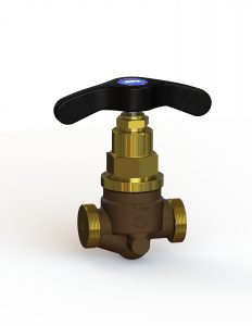
Globe valves operate as a linear motion valve to stop, start and regulate flow. The design incorporates a disc-to-seat ring contact at a perpendicular or 45-degree angle, to regulate the flow of gas or liquid either under or above the disc and seat, depending on the application, allowing for a tight seal. This capability allows globe valves the flexibility for use in both high- and low-pressure applications and eliminates potential seat leakage.

This reliability and flexibility explain why at one time, globe valves were utilized across industries more than any other type. As valve designs evolved, new designs better suited for various applications replaced globe valves in some instances. However, for a tight regulation of flow, the globe valve performs better than other types of valves, such as gate or ball valves. Determine whether a globe valve will best suit your flow parameters and requirements, and the best applications for its use.

Globe Valve Design and Operation

As its name implies, a globe valve is constructed with a round or spherical body, plus a seated disc and a vertical stem. The flow inside the globe valve is regulated by this stem’s movement, either up or down. And depending on its operational position, either fully or partially open or closed, the globe valve regulates the liquid flow within a pipeline.

The seats are designed to line up parallel with the flow of the liquid, utilizing its force to help seat the disc for a tight seal, without leakage. The farther the disc is positioned away from the seat, the more fluid will flow through the valve. The globe valve’s design and construction make it an ideal component for high-pressure and high-temperature systems.

The Importance of Directional Flow in a Globe Valve

The reason globe valves can operate in a wide range of pressure and temperature applications has to do with the way the disc operates. Globe valves used in low-pressure and low-temperature applications are designed to have the pressure flow under the disc. This directional flow allows the disc to rotate freely on the valve stem. The free rotation and low-pressure application allow the disc to fit snugly against the seat as the valve closes, for less leakage.

When pressure flows above the seat in a high-pressure and/or high-temperature system, this helps prevent the stem from contracting as it cools down, and also keeps the disc from lifting off the seat. A globe valve body should have an arrow indicator to point to the valve flow direction.

Globe valves come in a range of sizes, depending on the pressure and flow required. These valves can be either air or electronically actuated for reliability and better regulation. This actuation gives the globe valve another advantage over other style valves, such as a gate valve, which can be heavy and difficult to turn.

A globe valve can supply:

  • Automated actuation (shutoff) for greater reliability
  • A shorter stroke (compared to a gate valve)
  • Ability to:
    • operate under extreme temperatures, hot or cold
    • regulate flow of abrasive or caustic substances
    • regulate low- or high-pressure applications
  • Wide range of material options

Typical applications or industries for use of a globe valve would include:

  • Petrochemical for flow-regulated fuel oil systems
  • Industrial gas applications
  • Bulk filling in high pressure systems
  • Water cooling systems
  • Chemical feed systems
  • Steam vents, boilers and drains
  • Naval and commercial vessels (bilge suction or to prevent back flooding)

Types of Globe Valves Available

Globe Valve Design Based on Fluid Flow

The difference as explained earlier, is in the discs, and the method of closure or operation in accordance with the direction of the material flow, of either a gas or a liquid. A disc that closes against the direction of the flow offers a quick opening valve. Applications that require a quick closing valve might select a globe valve with a disc that closes with the direction of the flow.

Ball vs. Needle Disc Types

A ball disc globe valve is recommended for a low-pressure, low-temperature system. A needle disc is more often indicated for a high-pressure, high-temperature system

Z vs. Y Globe Valves

A Z style globe valve features a disc and seat that are perpendicular or sit at 90° to the pipe axis.

A Y-type of globe valve is designed to have the stem and seat of the valve at 45° to the pipe axis.

CPV Manufacturing offers its customers a wide range of globe valve sizes and material choices, with custom elements and design options available. CPV has the capability to design globe valves to handle specialty connections. Sealing integrity is built into any globe valve manufactured by CPV. For flexibility, reliability and a tight seal on a globe valve that will operate trouble-free for years, contact CPV Manufacturing today.

Bring the Hammer to a Standstill—Silent Check Valves Protect Pumps and Pipes

A silent check valve, sometimes called a poppet check valve, non-return valve or even one-way valve, might have different names but they all supply the same function. This type of valve helps control and protect against pressure surges in water lines, or reverse flow, and the potentially devastating consequences or effects on pipes and pumps. When a pump pauses or stops and the flow of liquid also abruptly stops, this in turn stimulates high pressure shock waves that, if unchecked, can damage the pump and pipes. A silent check valve, when functioning properly, prevents these shock waves and the knocking or banging that signifies a water hammer phenomenon, thus protecting pumps, pipes and surrounding equipment.  

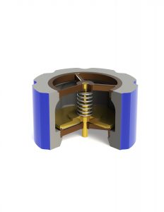
The operation of a silent check valve hinges on a spring assisted disc, engineered to close the valve the instant the forward flow of liquid ceases. This prevents reverse flow to eliminate water hammer.  

Consequences of a Water Hammer

Water hammer is a phenomenon that occurs when the pump shuts off and forward momentum propels the liquid on its course until offset by gravity or friction. When this happens and the liquid must suddenly either stop or change direction, this creates a shock wave or hydraulic surge. When a valve closes suddenly, and the water slams into it, this impact creates the water hammer that causes the knocking or banging sound inside a pipe after a pump abruptly shuts down.  

Depending on the size of the column of liquid and its speed, the force of this momentum is powerful enough to cause serious damage to capital equipment, such as snapping the pump shaft or bursting the pump casing or pipes.  

While this can occur during a single event, the effect can accumulate over time as the water hammer beats on the pump or the pipes, eventually resulting in ruptured pipes or a leak. This has the potential to create safety hazards for the workforce, damage surrounding equipment and/or cause extensive downtime and costly maintenance and repairs.  

 Other consequences besides water hammer could include over pressure from one side or potential contamination if the silent check valve is designed to prevent two different types of liquid from mixing together.  

Silent Check Valve Construction

Design and materials for CPV Manufacturing’s silent check valves conforms to the ASME Boiler and Pressure Vessel Code. Standard valve bodies are cast of carbon steel with trim of either stainless steel or brass, however silent check valve bodies can be manufactured of bronze or cast iron as well. The choice of material depends on the potentially corrosive nature of the liquid the valves are designed to regulate.  

 CPV supplies check valves in a range of smaller sizes up to eight inches in diameter as the largest available. Most of in line piston style check valves are a low-pressure flange connection that meet the ANSI B16.5 flange bolt pattern, in class 125 to class 1500 (pressure).  

 Each has a spring-actuated disc that opens when flow starts and automatically closes when flow stops. The reliable checking action, designed and engineered into each valve, will not allow flowback. While a check valve isn’t a safety valve per se, it is critical to system performance and reliability.  

 All of the silent check valves manufacturing by CPV are fast closing, offering a: 

  • Sealing, bubble-type shut off 
  • Quiet operation 
  • Wide pressure range 
  • Broad temperature range 
  • Decades of leak-free and trouble-free operation  

 The full flow design offers good flow rates through CPV silent check valves, to minimize head loss and pressure loss. Both help increase the valve and overall system efficiency.  

Description of Check Valve Features

1. Helical Springs 

These springs are engineered to ensure proper and complete valve closure automatically at zero velocity, when forward flow stops and before the beginning of reverse flow. CPV uses springs that can provide the lowest stiffness or K-factor consistent with optimum silent check valve operation. The springs are engineered for a conservatively estimated lifespan or performance of at least 10 million closures. 

2. Guided Lift Design 

A two-point bearing guides the disc with widely spaced bearings both above and below the seating surface. This eliminates any potential of the SCPV silent check valve disc tilting or becoming misaligned.  

3. Full Flow Area

This design feature increases the valve’s efficiency and minimizes head loss.  

 Silent check valves are ubiquitous across industries and commercial buildings and compounds, found in pipelines and wherever there is a water system, including: 

  • Manufacturing or processing operations that use liquid or water 
  • Chemical processing 
  • Oil and gas industry 
  • Small communities 
  • Residential facilities 
  • Hospitals and universities 

Work With Us

Companies in the market for silent check valves can count on CPV for reliability. It isn’t uncommon for silent check valves manufactured by CPV to have seen continuous service for 50 years or more. Once they are installed, it is a “set it and forget it” durable valve that will not need to be replaced for years, and supply trouble free service in piping systems around the world.  

Top Considerations When Selecting a High-Pressure Relief Valve

High-pressure relief valves fulfill a critical safety function in multiple applications, ranging from petrochemical to power, marine and aerospace industries.  Regardless of the application, certain primary features can help guide engineers when selecting a durable high-pressure relief valve that will help avoid catastrophic failure to protect your workers’ health and safety while also preserving capital equipment.


High-pressure relief valve


What’s the Primary Purpose of a Relief Valve?

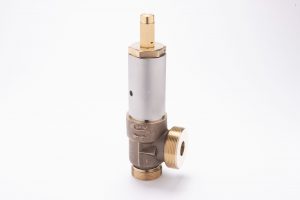
A relief valve functions as an operational safety feature, to help control and regulate the flow of high-pressure fluids and gases. It is designed to vent off extra pressure, whether from gas or a liquid. The design triggers the valve to open once a system reaches a predetermined set pressure.

This protects systems from experiencing pressures that exceed their design limits. Once a system reaches that predetermined level or valve set pressure, the relief valve opens, and a portion of the liquid or gas is removed from the system by diverting it through an outlet in the valve.

The relief valve helps maintain safe pressure levels to prevent potential damage or catastrophic failure. Once system pressure drops to its predetermined normal level, the relief valve closes or “reseats” until it is needed again. While a relief valve functions as a safety feature, it differs from a safety valve which only triggers in an emergency.

A safety valve opens instantly to its full venting capacity while a high-pressure relief valve opens gradually when system pressure reaches the preset level.

A catastrophic failure could mean loss of capital equipment such as pipes if the pressure doesn’t diminish. Pressure build up, if unrelieved, can lead to more serious consequences such as an explosion, potentially harming personnel and causing more widespread damage to equipment and surroundings.

High-pressure relief valves are found in several different industries including marine applications on naval and commercial vessels, aerospace, industrial gas, the petrochemical industry, power plants and many industrial applications as well.


Factors for Specifying a Relief Valve

There are several factors to take into consideration when specifying a relief valve. These can include:

1. Set pressure limit

The set pressure limit is the threshold that triggers the high-pressure relief valve action. For example, if the normal system pressure is 3000 PSI the engineer might determine the set pressure limit is 3300 PSI. Once pressure reaches that threshold it triggers the relief valve which then vents the excess liquid or gas. Consistent triggering of the relief valve often indicates a problem with the system.

2. Valve capacity

This relates to the amount of flow the valve is able to relieve.

Connection size and type—The connection of the valve or valve size needs to correspond to the size of the discharge piping. Operators must also determine the connection type for the inlet and outlet ends, typically threaded or flanged.

3. Shock and vibration

Material selection, design and testing will reveal the ability of the valve to withstand shock and vibration without triggering its action. Naval vessels require parts such as relief valves pass specifications for shock and vibration.

4. Environment

This particularly plays a role in material selection for the valve construction when it will come into contact with a corrosive or abrasive substance. An example of this would be a marine relief valve that can or will regularly encounter salt water. All CPV Mfg. high-pressure relief valve specified for marine purposes are manufactured of bronze.

5. Temperature

This factor impacts O-ring material selection. Depending on the temperature range, CPV can specify a specialty elastomer or material for the O-ring.

6. Orifice size

This relates to the relief capacity of the valve. When the orifice size is smaller, the relief valve can rate to a higher pressure but relieve less capacity. The larger the orifice, the lower the pressure but the higher the relief capacity of the valve.

7. Positive Reseating

All relief valves manufactured by CPV have a positive reseating, which means after it blows at pressure, it reseats itself or reseals once the pressure drops into the normal range. This reseating capability allows for continuous operations. Look for a soft seating design which acts as a bubble tight seal, versus a metal-to-metal interface, which can be prone to leaking.

8. Spring adjustment

A sensitive spring, such as those incorporated into a CPV high-pressure relief valve, allows the operator to adjust the release for a very narrow PSI range. For example, the spring itself might be rated for 1,000 to 2,000 PSI, but the sensitivity enables the operator to set it at a specific target, such as 1,015 PSI, for example.

Add to this testing capabilities, and the cooperative efforts of the engineering design team and the valve manufacturer can produce a valve with the most accurate control of the blowdown pressure setting.

Why Choose CPV Manufacturing? 

CPV manufactures relief valves in two different series: the 150 series and our flagship O-SEAL® line. The 150 series is a line of soft-seated female threaded relief valves with set pressures that range from the low end of 5 PSI up to 300 PSI.

The O-SEAL® line of soft-seated valves and separable fittings allow for positive control of high-pressure liquids and gases.  This line offers leak proof performance from vacuum up to 6000 PSI (414 bar).

CPV has been supplying high-pressure relief valves to the U.S. Navy for mission critical applications since the 1950s. Each individual valve built by CPV Manufacturing undergoes testing, not random or batch testing, but each valve.

Valves must meet a safety factor for the pressure rating of four to one.  If a valve is rated for 6,000 PSI for example, the valve strength is up to or in excess of 24,000 PSI. In addition, all valves meet the ASME Boiler and Pressure Vessel Code. Our valves are over-engineered to exceed the pressure strength rating, for the utmost in reliability.

Trust CPV Manufacturing for durable, reliable, high-pressure valves that meet the stringent requirements of the U.S. Navy, found in service in submarines, aircraft carries and other vessels throughout the fleet.  We can work within your specifications or consult for customized projects and applications.

Contact us today for a quotation.


A Pointed Solution for Precise, Regulated Gas Flow—the Needle Valve

Looking for an alternative to a shut off valve? An option that can supply you with some alternatives for more sensitive gas flow control? Companies can help minimize stress and strain on machinery and components by slowing gas flow in a regulated, orderly manner with a needle valve. This type of industrial valve is commonly used in gas filling, petrochemical and chemical processing applications.

Come explore the basics of needle valves including features and their applications in industrial gas and petrochemical processing.

What are needle valves?

Needle valves are a type of valve that is used to control the flow of fluid or gas in a system. It can be manufactured of stainless steel, brass or bronze. Its construction is comprised of a valve body, a stem and a small, tapered point called a needle or alternatively referred to as a plunger. They are known for precision and accuracy in flow control.

How does a needle valve operate?

The needle moves up and down via a knob or handle that is attached to the stem, similar to the action of a needle in a sewing machine. As the needle or plunger moves, it adjusts the size of a small orifice within the valve body. This in turn, regulates the flow of fluid or gas, as the opening within the orifice regulates or determines the amount of flow of fluid or gas.

This operation of a needle valve can be automated or adjusted by hand. In a manual operation, the handwheel controls the distance between the plunger and the valve’s seat. Turned in one direction, the plunger or needle lifts, opening the valve to allow fluid or gas to pass through. If turned in the other direction, the plunger decreases the opening in the orifice as it moves closer to the seat, to decrease the flow rate or close the valve.

An automated needle valve usually is connected to a hydraulic motor or air actuator. While larger manifolds might rely on automated valves, specialty gas filling operations often choose manual regulation to provide individual control for different gases. Needle valves from CPV Manufacturing for automated systems are pneumatically operated.

This style generally has low flow rates and a large pressure drop. This gives the operator the ability to throttle or better regulate gas flow.

Standard sizing for needle valves from CPV Manufacturing would range 1/8th inch tube size up to 2-inch pipe on the high end. In terms of pressure, there are two series of needle valves available. One is a 3,000-psi series while the other is a 6,000 psi series. Some select products of up to 7,500 psi also are available.

Desirable features for this type of valve

Needle valves have several features that make them a popular choice for industrial gas and petrochemical processing applications:

  • Precise flow control – allowing users to adjust flow rates with great accuracy. This makes them ideal for applications with critical specifications for flow control rates, such as chemical processing or pharmaceutical manufacturing or aeronautics.
  • High pressure capability – making them a popular valve in the oil and gas industry. Typical pressure ratings for needle valves can range from 3,000 up to 7,500 psi or more. Needle valves can be specified for high pressure gases including elusive gases like helium, hydrogen and oxygen.
  • Temperature resistance – designed to withstand high temperatures, making them suitable for use in applications such as steam systems or petrochemical processing.

Some of the most common applications for needle valves, over a wide range of industrial gas and petrochemical processing applications can include:

  • Aerospace
  • Chemical processing
  • Gas cylinder filling
  • Petrochemical processing
  • Pharmaceuticals
  • Propane systems

Companies know they can rely on CPV Manufacturing for the highest quality engineered equipment. For more than a century, CPV has specialized in supplying valves that fit the high standards and specifications of organizations from the U.S. Navy to the aeronautics industry and gas processing operations of all types. Investigate our valve selection to find a needle valve or other type that suits your operations.

New Ergonomic Valve Handles

Kennett Square, PA, USA (4/11/22) – Admiral Valve, LLC dba CPV Manufacturing Launches the Next Generation of Ergonomic Handles

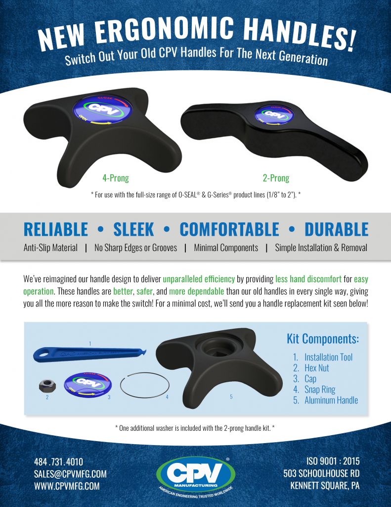
CPV Manufacturing has reimagined the design of its O-SEAL® and G-Series® valve handles to deliver unparalled efficiency to operations in piping systems. CPV is delighted to finally introduce the new, functional, ERGONOMIC handles to customers worldwide.


The next generation of handles provide less hand discomfort and easy operation to workers that maintain CPV valves on a regular basis. These innovative handles will now be included with the purchase of the full-size range of CPV O-SEAL® and G-Series product lines, in place of the old handles.

CPV’s Next Generation of handles are better, safer, and more dependable than the previous handles in every single way. With a sleek design, the new handles are made with an anti-slip material and utilize smooth edges, allowing for a better grip. This makes operating the valves that much easier. The handles are available in 4-Prong and 2-Prong configurations to suit specific valve sizes.

CPV manufacturing is 100% confident that these handles will provide lasting value to not only future customers who will purchase O-Seal® and G-Series® valves with the new handle, but also to previous customers. CPV is offering the opportunity for existing customers, who currently employ these valves in service, to switch out their old valve handles with the next generation.

For a minimal cost, CPV will send a replacement kit, fit for certain specifications, that includes an installation tool, hex nut, cap, snap ring, and an aluminum handle. Using the kit, customers will be able to replace their old handles in less than a minute and reap the benefits of the replacement for the entire lifespan of CPV valves (30+ years)!

To view how simple the installation/removal process is, CPV has created an in-depth YouTube tutorial to watch, here and an instructional blog to read, here.

If you have any questions or wish to order a handle replacement kit, contact CPV today at Sales@cpvmfg.com.


CPV Manufacturing LogoCPV Manufacturing was founded in 1915 as a one-man business, manufacturing replacement valves for steam-driven reciprocating pumps. Today, CPV is recognized worldwide for its high-quality valves and fittings and dedication to state-of-the-art design, equipment, safety, and reliability. CPV Manufacturing’s valves withstand the high tolerances required by the maritime, industrial gas, and petrochemical industries. Based out of Kennett Square, PA, USA, CPV has a complete facility for developing, manufacturing, and testing its products. Dedicated workers and global partnerships allow CPV to be a market leader. 

Installation and Removal of CPV&#8217;s New Handles

The process of installing and removing our new ergonomic valve handles for the full-size range of O-SEAL® and G-Series® product lines is so simple it can be done in under a minute! The ease of installation can be seen below in the step by step tutorial.

This specific bulletin shows the installation of a 4-prong valve handle; however, the same steps apply to our 2-prong valve handles. The only difference is and additional step due to an extra washer in the replacement kit, also shown below. During installation and removal of a 2-prong handle, the extra step would occur after step 2 for both.

Installation and Removal of CPV's New Handles


For extra guidance, we have listed all the removal steps below and made an in-depth YouTube tutorial showing just how simple the installation and removal of our new valve handles really are!

Removal Steps:

Step 1: Using the Handle Installation Tool, pick out one end of the Snap Ring and lift it out of the groove. Be sure to place your hand over the ring to keep it from flying away and becoming lost.

Step 2: Remove the Cap covering the Hex Nut.

Step 3: Remove the Hex Nut with a Socket Wrench. The handle should then come right off the valve.


Feel free to contact us at Sales@cpvmfg.com or 484.731.4010 if you have any other questions!


CPV Manufacturing LogoCPV Manufacturing was founded in 1915 as a one-man business, manufacturing replacement valves for steam-driven reciprocating pumps. Today, CPV is recognized worldwide for its high-quality valves and fittings and dedication to state-of-the-art design, equipment, safety, and reliability. CPV Manufacturing’s valves withstand the high tolerances required by the maritime, industrial gas, and petrochemical industries. Based out of Kennett Square, PA, USA, CPV has a complete facility for developing, manufacturing, and testing its products. Dedicated workers and global partnerships allow CPV to be a market leader.